
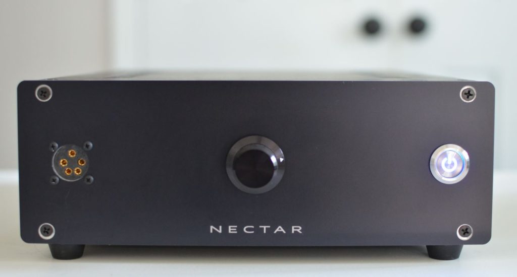
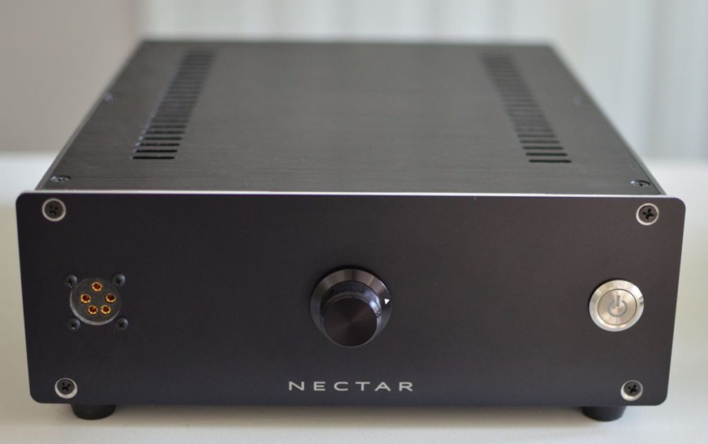
The Nectar Agave Electrostatic Amplifier
I designed this amp and releasing the design, mostly because it’s what I enjoy doing. If you’re an experienced electrical engineer or equivalent hobbyist with safety in mind you can review the design and see if you want to build it. I really have no time to build headphones AND build amps so I don’t sell these amps but I do have PCBs that would go for around $40 – $50 or so depending on what you need, if it makes it easier for you.
Design Concept
Recently I built the KGSSHV and it is also a stellar amplifier, but for me it was a bit of a struggle to build, very technical, complicated, costly and getting harder and harder to source components. I made a mistake on the first power supply and almost gave up a couple of times, but built another one and it worked. My very first amp was the opposite, very cheap to build, worked the first time every time, everything fit on one board and it performed well for the cost and simplicity. But there were some noticeable improvements that could be made. The Agave amp is somewhere in the middle. It has everything it needs to perform very well, with margin, without being overkill. The added cost, space and effort is targeted to places where it would make the most difference in performance.
One of the main challenges with electrostatic amplifiers is that they are driving a capacitive load (unlike an inductive load with traditional speakers). There is a misconception sometimes that since it is a capacitor that they “draw virtually no current” and don’t need much power. This is not true because the headphone impedance will follow the formula 1/(2*pi*f*C). Where f is the frequency and C is the capacitance of the headphone. Therefore the impedance will change proportionally with the audio frequency. At 20kHz and assuming a 150pF load, is about 53k ohms. At say a 400V peak going into 53k this is about 7mA. About 3 Watts, and multiply that by two legs (-R and +R) and then two channels (L and R), and you have quite a lot more power needed compared to a traditional headphone. And at high voltages, components can become quite large.
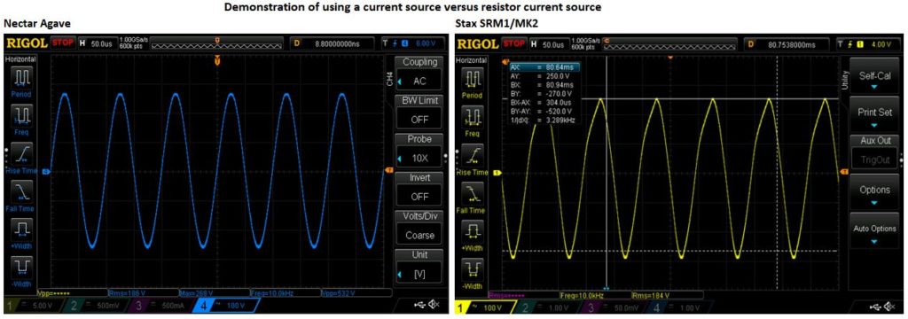
Unfortunately the current is just a bi-product of creating the voltage, but the voltage is what is creating the electrostatic force needed to drive the headphones. Some amplifiers, such as the SRM1/MK2, and also one of my very first designs, use “resistor current sources” meaning that pulled up to the high side rail is a large resistor (usually around 50k Ohms). This saves a lot on space and costs less but at high voltages, and high frequencies, the amp can’t keep up with the slew needed to charge and discharge the capacitance through a large resistor. This appears as voltage distortion that can be seen on an oscilloscope, and heard as sharp sibilance at higher volumes. If there is enough open loop gain in an amplifier, one could add a large amount of global feedback, but this feedback requires compensation to ensure loop stability and this could make the signal a bit more sluggish. These are all normal design challenges every electrostatic amp has to deal with.
The Agave amplifier is inspired by the Nelson Pass “Zen” speaker amplifier where a single FET operating in Class A is used to drive the load, similar to how a Triode is used in a tube amplifier. This concept does not use any global feedback but a small amount of local feedback to stabilize the loop. A true top side current source is used instead of a resistor current source. Using a current source instead of a resistor adds a lot of open loop gain to the circuit, which makes the local feedback have much more headroom to work better, and it also provides enough bias current to keep up with the slew needed for high frequencies. Finally, driving a single FET can be challenging at high frequencies due to something called the Miller effect. Which is where the output capacitance of the FET gets multiplied by the gain of the amp, so the pre amplifier circuit needs to be able to drive a large amount of FET capacitance. The way I get around this is by doing what’s called a Cascode design, where another FET is added beneath the output FET to drive and buffer the output FET.
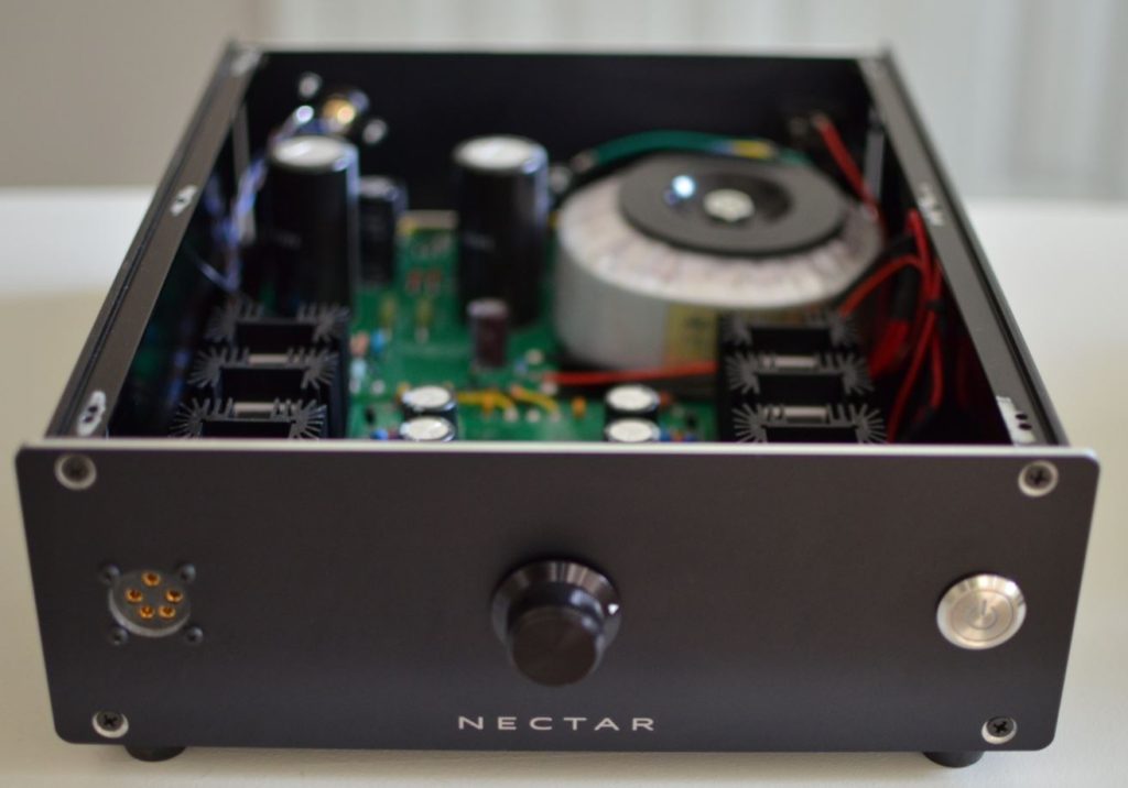
Where I saved space and cost is with the power supply. The high voltage supply is not actively regulated and is designed like a vacuum tube amplifier power supply. A large 600VAC transformer is used and RC’s are used to provide the +/- 390VDC needed to drive the circuit, and very large capacitance (overkill really) is used to remove any voltage ripple and ceramic caps are used to remove any high frequency noise. The supply is just as stiff as a regulated supply. The main “disadvantage” is that +/-390V can be slightly higher or lower depending on how high or low your mains 120VAC is. But this is not really an issue since current sources are used, the bias current will always be the same. The low voltage rails for op-amps and signal level audio are 14V and 7V and are fully regulated and filtered.
The +600V or +580V selectable bias voltage for the diaphragm is done with voltage doublers and zener diodes. This is a very typical method but I made sure that the capacitors used in these doublers are large enough to really maintain that very high voltage under load (which is a series resistor and Zener’s) such that there is enough current to bias the Zener’s properly to give their true voltage output. So you really do get exactly a 600V or 580V with no ripple, depending on what you select with the circuit.
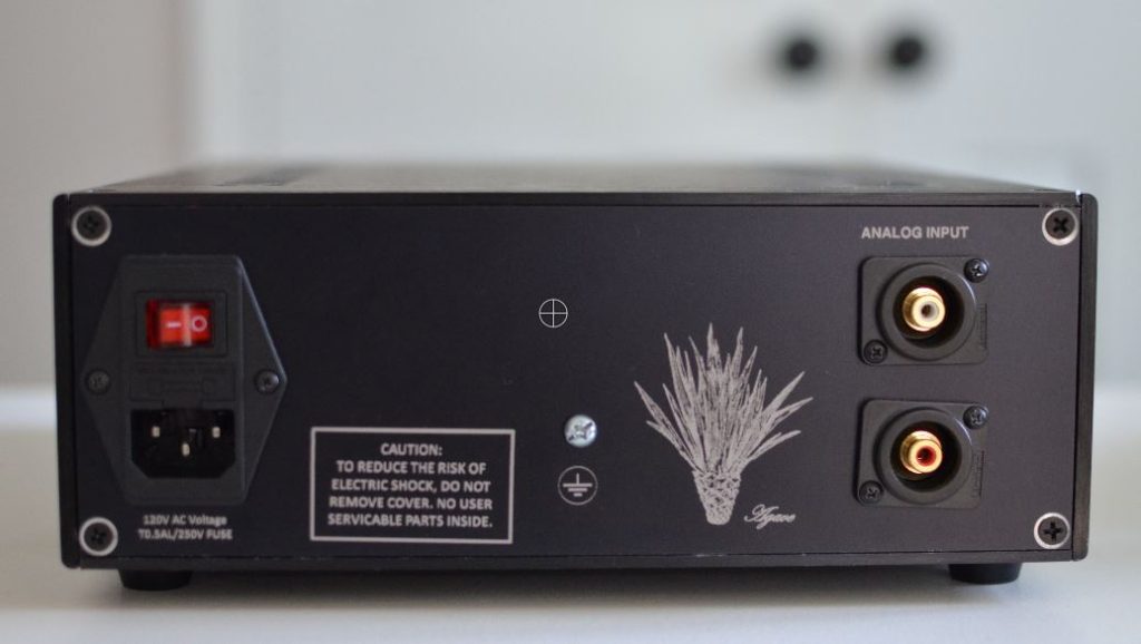
I use CL90 current limiters at the input of the supply to limit the inrush current so that the fuse can be properly sized for safety. I etch away some metal oxide so that metal on metal contact can be made to ensure full continuity in conductivity of the chassis. I then tie the chassis directly to earth ground for the mains plug. The ‘secondary ground’ or signal ground (which is derived from the isolated secondary of the main transformer) is also grounded to earth via two back to back diodes and a 330 Ohm series resistor which is a common strategy to enhance safety and prevent ground loop hum.
Measurements
Typical amplifier measurements are characterized with distortion at 1kHz and a frequency response measurement with the assumption that the distortion is maintained across the entire frequency band, but this is not applicable for electrostatic amplifiers given the points already discussed, so a better way is to provide a range of distortion across frequency. I measure my amps using a Stax SR-407 for consistency which has about 95pF, the HiveX has about 93pF of capacitance.
Input: Single Ended RCA
Max Input voltage before clipping at full output volume: 0.51Vrms
Gain: 59dB
Frequency Response: 20Hz to 20kHz
Max output voltage: 280Vrms
THD+N @ 100Vrms: 0.03% 100Hz, 0.05% 1kHz, 0.07% 10kHz, 0.05% 20kHz
Bias Voltage: +580VDC (Pro-Bias) or +600VDC configuration possible.
Here’s an example of the Agave (left) versus the SRM1/MK2 (right) showing the difference between using a current source versus a “resistor current source”. Even at 10kHz at high voltages, the distortion is visibly noticeable. Note: This is an SRM1/MK2, a pretty great vintage amp for its time, but other amps that use top side resistors, or tube amps for example, could get around this by adding a large amount of global feedback.
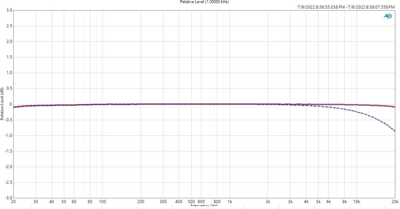
Frequency response is shown below (red) is flat as you would expect from an amplifier. The Cascode design helps get around the Miller effect that would otherwise roll off the highs significantly. The measurement is taken before two output protection resistors at 5.1k ohms each. These are there for some common sense protection and buffering from the very strong drive of the amp and are included and recommended by the KG DIY amps. However they introduce an unavoidable small RC roll off (blue dotted line) with the “R” of the 5.1k and the capacitance of the circuit, headphones and measurement instrument. It is -0.8dB at 20kHz so it is inconsequential but I spent some time trying to determine what was causing it.
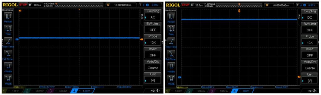
Here’s the +390V rail while playing audio with an AC coupled measurement so you can see that there is no ripple on this supply. And also on right is the bias voltage set to 600V (reading about 604V). This is measured before the ballast resistor as it is not possible to measure it accurately after the large 4.7Meg ballast (the scope probe loads it down with 20Meg).
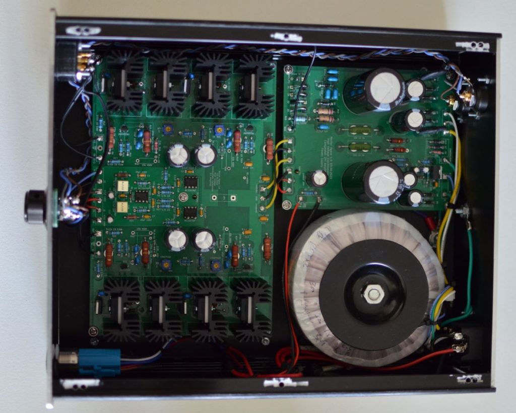
Schematic & BOM
The files below should have everything needed. The chassis is in the Power Supply BOM section and I got it from Ebay. It is a snug fit so you have to be careful about how you align everything. I had to edge the audio amp to the left so I could fit the switch without it interfering. I used front panel express to have the front and rear panel machined. Not included is the Stax 5 pin plug which I make myself, if you want one let me know or you can probably find one online. Note that for the audio amplifier build, R39,C28,C23 and their equivalent counterparts on the other legs were intended for loop compensation, but after the square wave test, they weren’t needed, so they were depopulated. For the first build, the Cascode FETs (Q13-15) I used STP5NK100Z instead of AUIRF3305 so I have not tested it with AUIRF3305 because they got damaged when I forgot to populate JP1-4 (jumpers) to close the feedback loop. For R8,9,29,30 I used 510k instead of 270k which had less power dissipation. This is indicated in the BOM. Please note that nothing on here is professional advice and please review my disclaimer page.
Some notes 2/24/26
Note: I do consider this portion of my site as kind of “free information”. So if you do decide to build this, use this information as you wish and while I will try my best to answer your questions and requests as a fellow hobbyist, please keep in mind that this portion of my site is a not for profit, and I have to balance my time prioritizing headphone customers.